
Micromet Pot Feeders
Description:
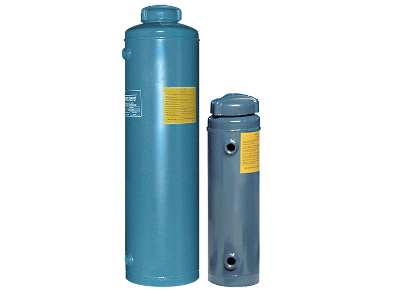
The No. 20L and No. 100L Micromet Pot Feeders are designed to slug or shot-feed chemicals into chilled water systems, hot water boilers, steam boilers, etc. The tank is composed of 11 gauge (20L) or 10 gauge (100L) Steel while the caps are cast iron. Other installation items such as the shut-off valves, elbows, nipples, strainers, tees, drain cocks, flow indicator, etc. are not included.
The feeder can also be used to introduce Micromet into commercial potable water systems for control of scale, corrosion and red iron staining. When doing so, it is necessary to utilize strainers and the FS01-7P Pyrex Flow Indicator. The flow indicator consists of a transparent Pyrex cylinder, containing a rubber ball, fitted in two castings having 3/4˝ female connections at each end.
| Packaging Size | Part Number | Additional Info |
|---|---|---|
| No. 20L Feeder | 4628-0 | |
| No. 100L Feeder | 4650-0 |
Directions:
It is important to install the feeder on a bypass arrangement (See Fig. 1 on Bulletin 3-404. Download by clicking on the "Product Information" tab.) particularly when feeding Micromet. In fact, when feeding Micromet, the feeder should be installed in a bypass on the COLD water line to the equipment to be protected. When putting Feeder before a water heater, place far enough away so that hot water will not flow back into Feeder. On private well systems where iron is present in the water, the Feeder must be installed before the water storage tank.
- Install Feeder in a convenient location where it can be refilled easily. Ensure that there is no strain placed on the flow indicator.
- Use 3/4˝ pipe between Feeder and the water line to be treated.
- A flow control valve, “A”, must be installed in the water line between the inlet and outlet connections to divert a portion of the water flow through the Feeder.
- 3/4˝ shutoff valves, “B” and “C”, are required to isolate the Feeder when recharging. Where an anti-back siphon age device is required, a check valve should be installed at “D” in main line before Feeder.
- Insert a strainer in the bottom inlet opening and a strainer in the top or outlet opening in the side of the feeder tank. A drain cock should be installed in a tee, as shown in Figure 1, to drain water from the feeder when necessary.
- Unions must be used on both inlet and outlet lines to facilitate removal of strainers for inspection and cleaning once a year.
- The flow indicator is installed so that water will pass vertically up through indicator. Do not twist or place flow indicator where it will be under strain.
- After installation is completed and tested for leaks, close valves “B” and “C”, remove filler cap, and drain water from Feeder through drain cock.
- Remove the filler cap by turning counter clockwise.
- Fill Feeder with recommended amount of Micromet.
- Close drain cock, crack the inlet valve “B” slightly and fill the Feeder completely with water. Close valve “B” and replace filler cap.
- Replace filler cap and secure.
- Open valves “B” and “C”.
- With water turned on so that it is being used at the maximum rate, valve “A” should be closed to the point where the flow indicator ball is raised and spins rapidly. When water is used at low flow rates, the ball should revolve slowly.
Product Information:
Literature Downloads
Download the product bulletin and other relevant literature here.
Labels
Download a low resolution file of the product label here.